You've Reached the Center of the Internet
It's a blog
Building RF Circuits
Since my last post about RF, Phil and I have taken some steps forward. I've built two simple RF circuits: a 20dB attenuator and a return loss bridge. Do they work? I'm not sure, exactly. The attentuator's purpose is to decrease the amplitude of a signal. It definitely does that, at least to some extent. Whether it does so by 20dB is in question.
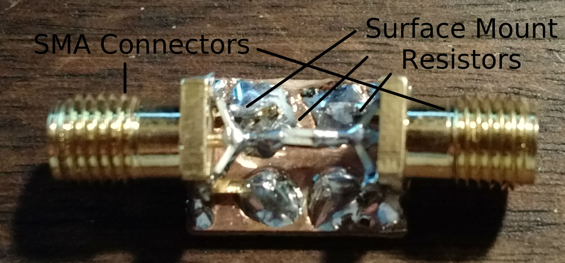
Attenuator
The return loss bridge is a bit mysterious. It has three coaxial inputs. One for an RF signal, one for a test load, and a third for a detector. The output measured by the detector should be related to the part of the signal that's reflected by the load. It seems like it might be working too.
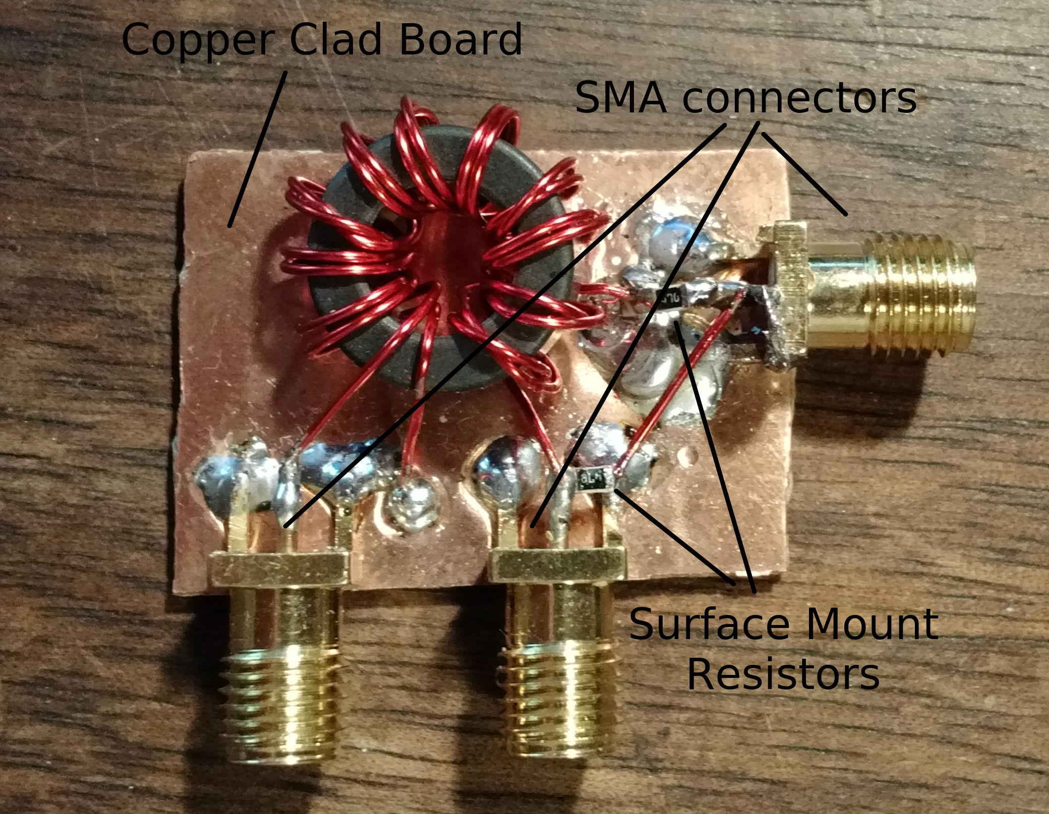
Return Loss Bridge
The purpose of this post is to record the RF circuit building techniques we've been using.
You want to build on copper clad board, with the copper surface itself acting as a ground plane. You can solder SMA connectors directly to the ground plane. To reduce non-ideal behavior at high frequency, you want to use components with short leads, ideally surface mount parts. Having short leads means keeping the whole thing compact. You can fiddle around with layouts until you find one that keeps leads short.
Ideally, there's no wire and the components themselves bridge all the gaps, as with the attenuator. Once you've chosen a layout, you can estimate the area of it and use tin snips to cut that size piece out of a copper clad board. Then just solder it together and try not to mangle it too much.