You've Reached the Center of the Internet
It's a blog
ZIPY — A Homebrew Inverted Pendulum and Control System

Phil and I have been working on this one for a long time. We're calling it ZIPY: Zippy Inverted Pendulum Yakshave. We finally succeeded in controlling an inverted pendulum. It swings up and balances. Would ya look at that! Also check out Phil's posts on the project.
The inverted pendulum or cart pole is a classic problem in control theory. It's in OpenAI Gym of course, but we wanted to see it work in real life, not some lame simulation. We were inspired by Russ Tedrake's class on underactuated robotics and by the popularity of the problem for reinforcement learning.
A Real-Life Cart Pole
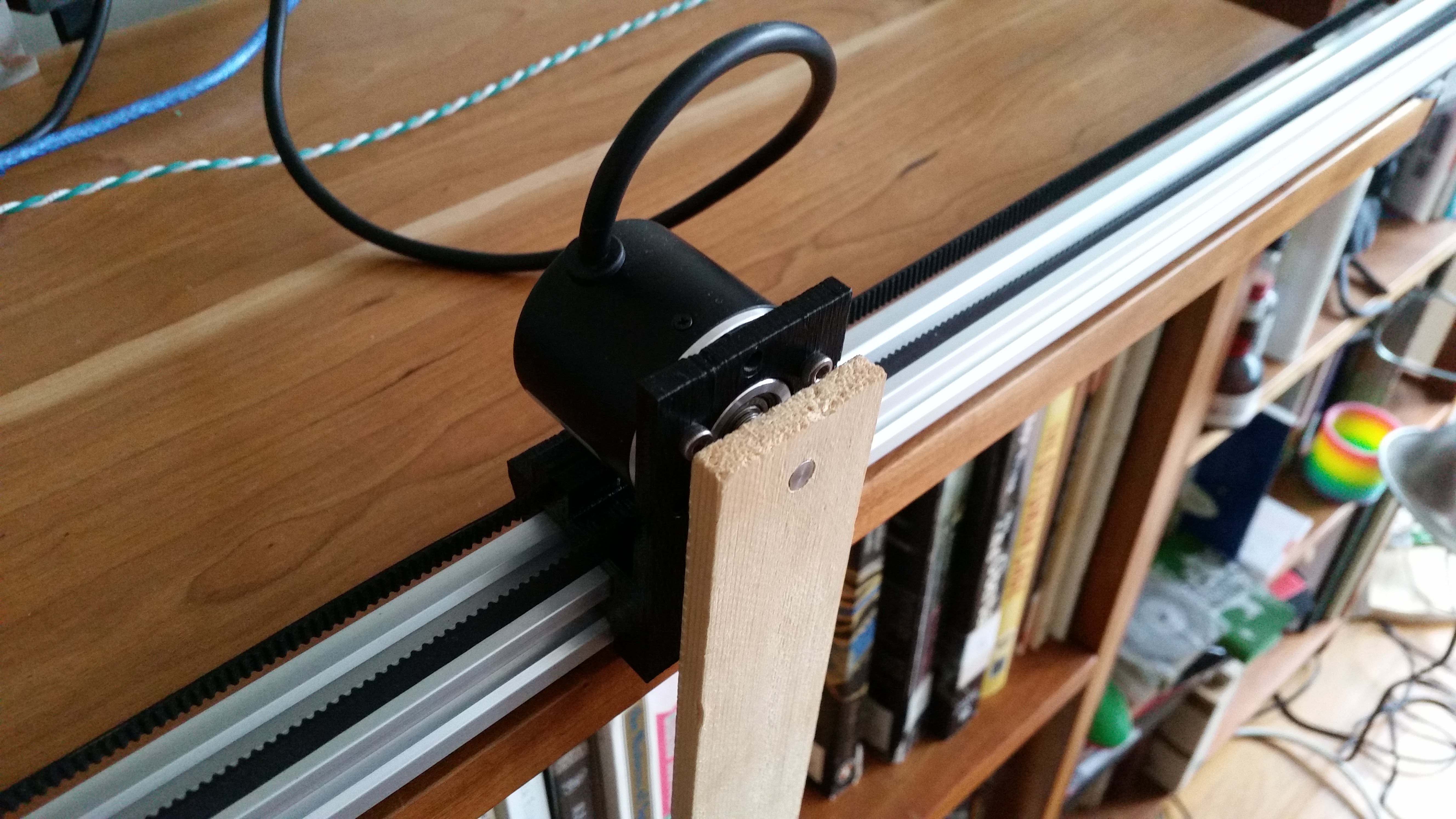
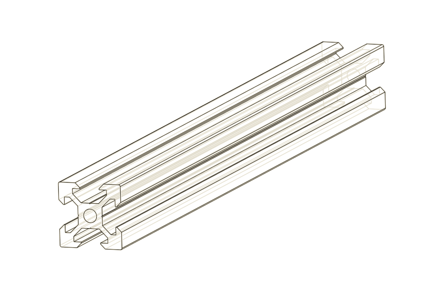
It took a few iterations, but we eventually found a system that works well. Our cart is 3D printed PLA driven by a DC motor via a toothed belt. The pole itself is a paint stirrer. One of the longer type, about 24". A rotary encoder opposite the motor acts as a pulley for the belt and allows us to track the motion of the cart, while a second rotary encoder on the cart is a pivot for the pole and measures its angle. The motor is controlled by a 32 amp Sabertooth motor controller. It's overkill, and pretty expensive at about $120, but we already had it for another project. We monitored the encoders with an Arduino. The foundation of the system is a piece of extruded aluminum rail called V-Slot, on which the cart slides and the motor and encoder are mounted. Our rail is 1.5 m long, from a company called SMW3D.
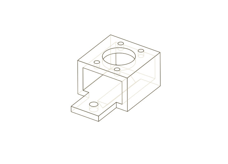
We used a 3D printer to make a PLA cart with mounting points for a rotary encoder and grooves to lock in a toothed belt. We designed all of our parts in Onshape. It's my favorite.
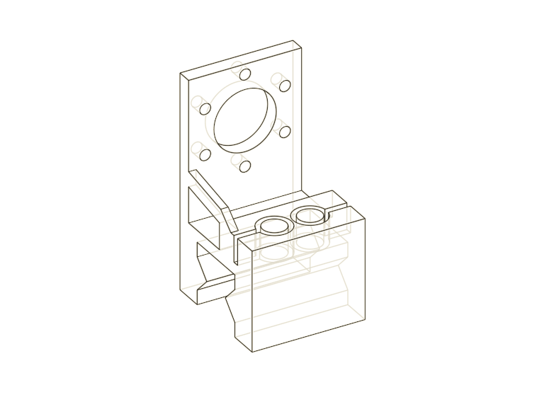
We found that if you slide the cart onto the V-Slot and dunk the two in boiling water for a moment, you a good fit for sliding with no fancy bearings. A touch of 3-in-1 oil seems to help as well. We also printed some pieces to mount the motor and rotary encoder to the rail. All of the designs can be found in our Onshape project.
The Software
All the software can be found in our Git repositiory. The rotary encoders were monitored by an Arduino Uno. Rotary encoders produce pulses on their two outputs as the shaft rotates. The pulses occur at regular intervals as the shaft turns, and the relative timing of the pulses give the direction of rotation. Driving them is just a matter of counting and interpreting these pulses. Normal operation requires two interrupt pins per encoder, but you can get away with one if you're willing to accept half the resolution. That's what we did because the Uno only has two interrupt pins. We still got 600 positions per revolution of resolution. Good enough. The microcontroller counts these pulses and keeps track of position by dead reconing. The program sends the current encoder positions whenever it receives a query over serial.
On the other side, a Python program contains all the smarts. It commands the motor controller over serial and can poll the Arduino whenever it needs to know the state of the system. We used two different controllers, a controller to pump energy into the system and swing the cart into the upright position, and an linear quadratic regulator to balance it upright.
The LQR Controller
The balancing controller is called an linear quadratic regulator or LQR controller. Phil wrote a more detailed explanation of the math involved, but here's an overview. It's an optimal controller for a linear system in a state, $$x = \begin{bmatrix}q\\\dot{q}\\\theta\\\dot{\theta}\end{bmatrix},$$ with control input, $$u = \begin{bmatrix}f\end{bmatrix}$$ equations of motion, $$\dot{x} = Ax + Bu,$$ and a quadratic cost function, $$c = x^T Q x + u^T R u,$$ Where \(q\) is the position of the cart, \(\theta\) is the angle of the pole counter-clockwise from vertical, \(f\) is the force on the cart, \(A\) and \(B\) are matrices that define the dynamics, and \(Q\) and \(R\) are matrices that define the cost.
To obtain the LQR controller, we first found the equations of motion. We assumed that our pole was light enough that it didn't significantly affect the cart's motion, reducing the free parameters to just \(\theta\) and \(\dot{\theta}\). The only forces on the pole are due to gravity and the motor. The torque on the pole from gravity is \(\tau = \frac{mgl}{2} \sin{\theta}\), so the angular acceleration is \(\ddot{\theta} = \frac{\tau}{I} = \frac{m g l}{2I}\sin{\theta} \approx \frac{m g l}{2I}\theta\). The torque on the pole from the motor is identical to that of gravity, but turned 90 degrees in \(\theta\), so \(\ddot{\theta} = \frac{m \ddot{x} l}{2I}\cos{\theta}\ \approx \frac{m \ddot{x} l}{2I}\). The effects of gravity end up in \(A\), $$A = \begin{bmatrix}0 & 1 & 0 & 0\\ 0 & 0 & 0 & 0 \\ 0 & 0 & 0 & 1 \\ 0 & 0 & \frac{m g l}{2I} & 0\end{bmatrix},$$ and those of the cart acceleration end up in \(B\), $$B = \begin{bmatrix} 0 & 1 & 0 & \frac{m l}{2I}\end{bmatrix}.$$ The controller \(K\) allows you to find the optimal control input for a state \(x\), $$ u = -K x.$$ You can find \(K\) by solving a nasty equation for \(P\), $$A^TP + PA - PBR^{-1}B^TP + Q = 0,$$ and plugging into, $$K= R^{-1} B^T P.$$ Luckily, there is a SciPy function that does it for you.
The Swing-Up Controller
A clever trick allows us to pump energy into the system when the energy is below the target energy (the energy of a motionless pendulum, standing straight up), and suck energy out when the energy is above the target. $$f = (E(x)-E_{target}) \dot{\theta} \cos(\theta)$$ Imagine the cart is below the energy threshold and moving counter-clockwise. You want to apply a counter-clockwise torque to increase the rotation speed. If the pole is above the horizontal, that means pushing the cart right with a positive force. If it is below the horizontal, the cart should be pushed left. This flip is captured by the \(\cos{\theta}\). Flip the sign of the diffence from target energy or the current direction of rotation, and you also want to flip the input. So overall, this equation always provides the right direction for the force. Pretty neat!
Videos
What didn't work
We tried monitoring the position of the cart and pole using an OpenCV vision system. We put large colorful stickers at the top and bottom of the pole, and looked for areas in the images with those colors. You can see in our images that we had all kinds of junk in frame along with the pendulum. By choosing the right colors and removing prolematic objects, we were able to make this work. It was very annoying, though. As light changed in the room, we had to recalibrate the system often.
There was a bigger problem, though. We discovered that OpenCV (or possibly the drivers of the webcams we tried) introduced a five frame buffer, which caused a five frame delay. We never figured out a way around this and we never succeeded in controlling the system with this delay.