You've Reached the Center of the Internet
It's a blog
Homemade Yagi-Uda Antenna
I’ve been getting into radio again. Phil and I pulled out our old handheld Baofeng radios and tried to reach each other from our houses. He wrote up a post on this too. The radios we have are dual-band, meaning they can transmit and recieve on the 70 cm UHF band and the 2m VHF band. By the way, we both have ARRL Technicians licenses, which are required to transmit in these bands.
We live about a half-mile apart and we found we could hear each other on 70 cm band but not the 2 m. Both of these bands are said to require line of sight. I can’t literally see Phil’s house from mine, but the 70 cm band worked anyway. I guess this means my signal is bouncing around a bit and eventually finding its way to Phil.
We did this experiment using the stock rubber ducky antenna. These are omnidirectional, so they transmit evenly in all directions within the plane normal to the antenna. If you know where your target is, this is sort of wasteful. You’re spending some of your transmitter’s power in the wrong direction. I thought it would be fun to build a directional antenna for 2 m and see if we could reach each other’s houses. We built a simple antenna design called a Yagi-Uda.
The Yagi-Uda design is probably familiar to you, classic roof-top TV antennas are Yagis.
It consists of a feeder element, which is a pair of conductors that are driven by the radio transmitter, a reflector, and one or more directors.
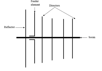 The reflector and directors are just passive conductors but they react to the driven element and contribute to the overall output.
The Wikipedia article has a nice animation that might give you a sense of how the elements work together.
The Build
We built a tape measure Yagi. This is a common method for hobbyists and I think it’s really clever. You cut up a tape measure to form the conductors. This has a few benefits. It’s easy to cut. The measurement device is built in. The antenna ends up being flexible and collapsable. You might even have a spare tape measure lying around.
We used the dimensions from an Instructables page which seems to be based on someone else’s design. There are tons of designs out there.
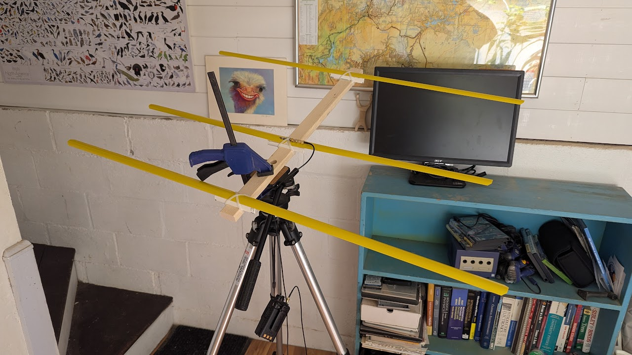
Here’s what we ended up with:
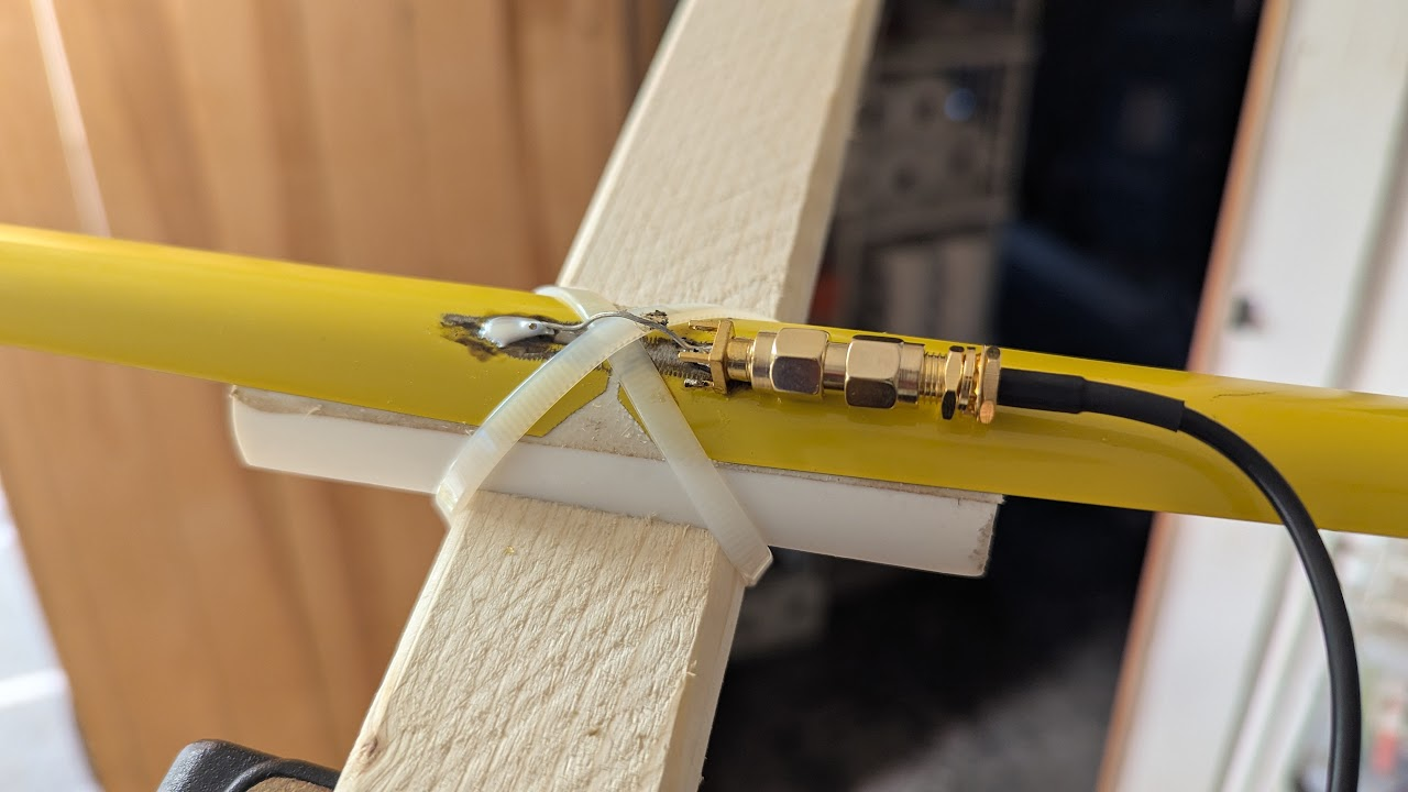
We used pieces of PVC pipe and zip ties to mount the tape measure segements to a wooden boom and soldered an SMA connector across the driven elements.
There are pieces of double sided tape between the tape and the PVC to keep things from sliding.
Tuning
The antenna is designed to work at 145 MHz, which is within the 2 m band. That doesn’t mean that the antenna is ready to use at 145 MHz, however. If the antenna’s impedance doesn’t match the transmitter’s impedance, energy will be reflected back into the transmitter. This could damage the transmitter.
There are different ways of measuring the reflected power, but the most common seems to be Standing Wave Ratio or SWR. SWR is the ratio between the minimum and maximum amplitude of a standing wave in a transmission line. A SWR of 1 means perfect transmission. An SWR of infinity meanse perfect reflection. Online sources suggest that an SWR of less than 2 is a good goal for a radio antenna.
You can buy a standalone SWR meter, but Phil got us a more general instrument called a Vector Network Analyzer or VNA.
Specifically, he got a NanoVNA.
It’s really cool, I highly recommend getting one if you’re into radio at all.
Essentially, it measures the complex impedance of the circuit you connect it to over a range of frequencies.
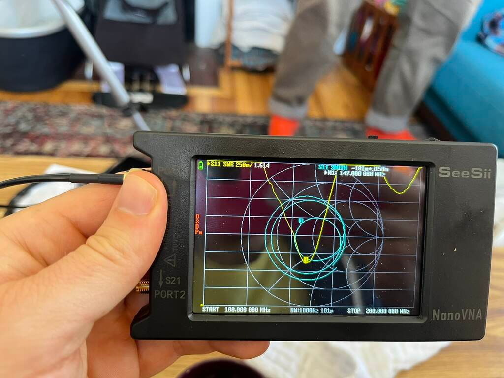 In the image above, the VNA shows two traces.
In yellow is the SWR measured directly.
It shows that at 147 MHz, the SWR is 1.614.
Not bad.
In the image above, the VNA shows two traces.
In yellow is the SWR measured directly.
It shows that at 147 MHz, the SWR is 1.614.
Not bad.
The teal line shows what’s called a Smith chart.
This is a way to plot complex impedance transformed such that a purely resistive 50 Ω load is the center, a short circuit is on the left, an open circuit is on the right, and purely reactive loads are at the top and bottom.
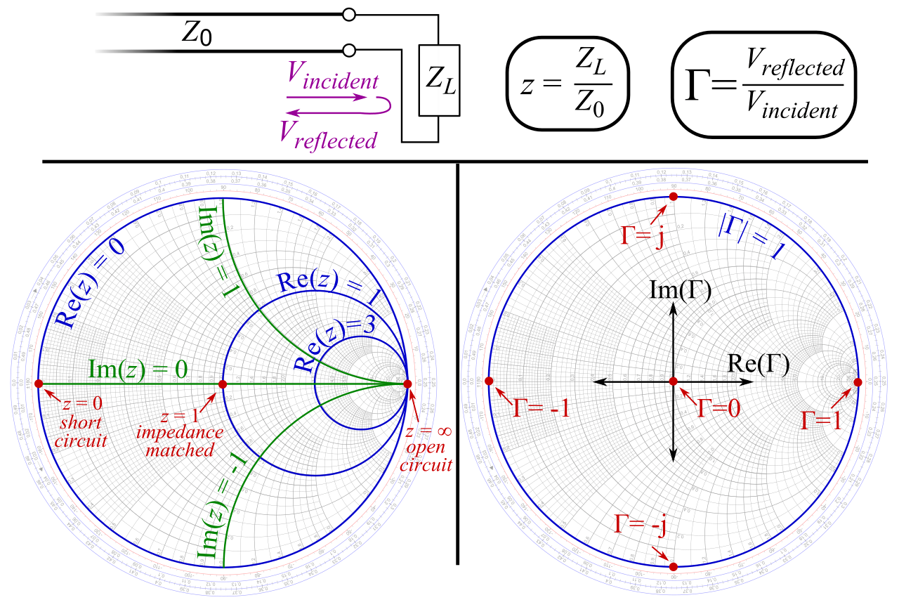
That 50 Ω load is important because that’s the typical output impedance of a radio transmitter. If the antenna’s impedance falls in the center of a Smith chart, the impedances are pefectly matched. In the VNA image above, you can see that the indicated point on the Smith chart trace is close to the center. That means our antenna was well matched to the transmitter. That’s lucky, because we didn’t have a great sense of how we’d tune the impedance if we needed to. These measurements gave us the confidence to plug the antenna into the Baofeng. I turned the transmit power to low just to be safe.
Radiation Pattern
With the antenna built, we decided to try to measure the radiation pattern. That is, measure how much power is emitted at each angle. We mounted the antenna on a tripod and used an RTL-SDR USB radio reciever to measure recieved power.

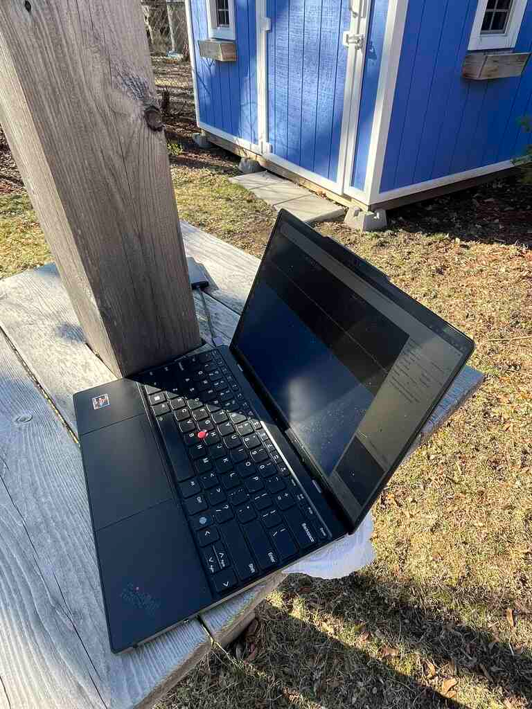
We rotated the antenna in 10° increments and measured the power at each angle.
Here’s the radiation pattern we found.
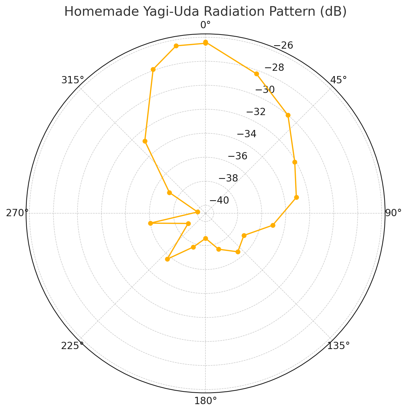
Looks reasonable when compared to other references I’ve seen for Yagi-Uda radiation patterns. One interesteing feature is the asymmetry. We think this may have been caused by my house. In these coordinates, it is located between about 20° and 90°. I believe it reflected a bit of the signal back toward the reciever.
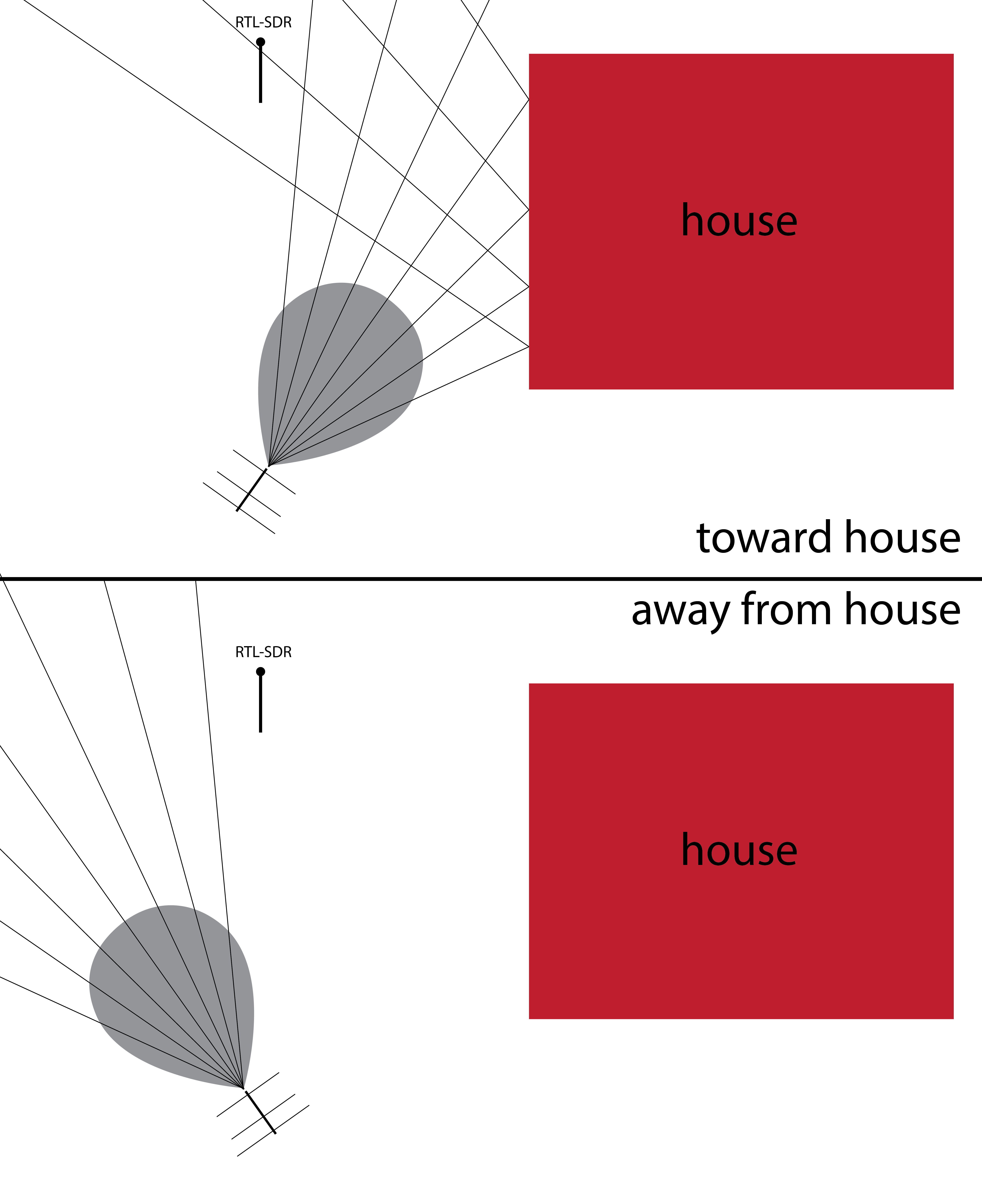
We’ll have to try this out in an empty field.